One of the pesky problems in railroading is the slippage that occurs when rounding a curve due to the fact that the wheels are fixed to the axle and the wheels run on rails of different length. This increases the load on the locomotive to pull the train around the curve due to the sliding friction. The prototype railroads reduce the problem by lubricating the sides of the rails on difficult pulls. This is not practical on our small rails. For a 65 ft. radius track the slippage is approximately one inch for each 10¯ of arc. Slippage is primarily on the outer wheel because the inner wheel has the additional friction of the flange on the rail caused by the pull of the locomotive as the train rounds a curve. This slippage contributes to wheel wear.
Various solutions have been tried by live steamers. Usually it involves floating one wheel on the axle and let the other remain fixed to the axle. This was tried on the tender of one of us using Garlock DU sleeve bearings. After about two years of operation the wheel wobbled badly due to bearing wear. When rounding a curve the side force on the wheel causes the bearing to be loaded on the two opposite ends which is aggravated by the short length to diameter ratio (L/D) of about one or less. Sleeve bearings are not intended to take a moment load. The usual bearing application is to use two bearings on a shaft resulting in a radial load on each bearing. This same scheme was tried in the early days of railroading using a large wheel hub with a rather long bearing. This design was patented in 1863. The idea was abandoned because of the problem of bearing wear which let the wheel wobble and result in derailing.
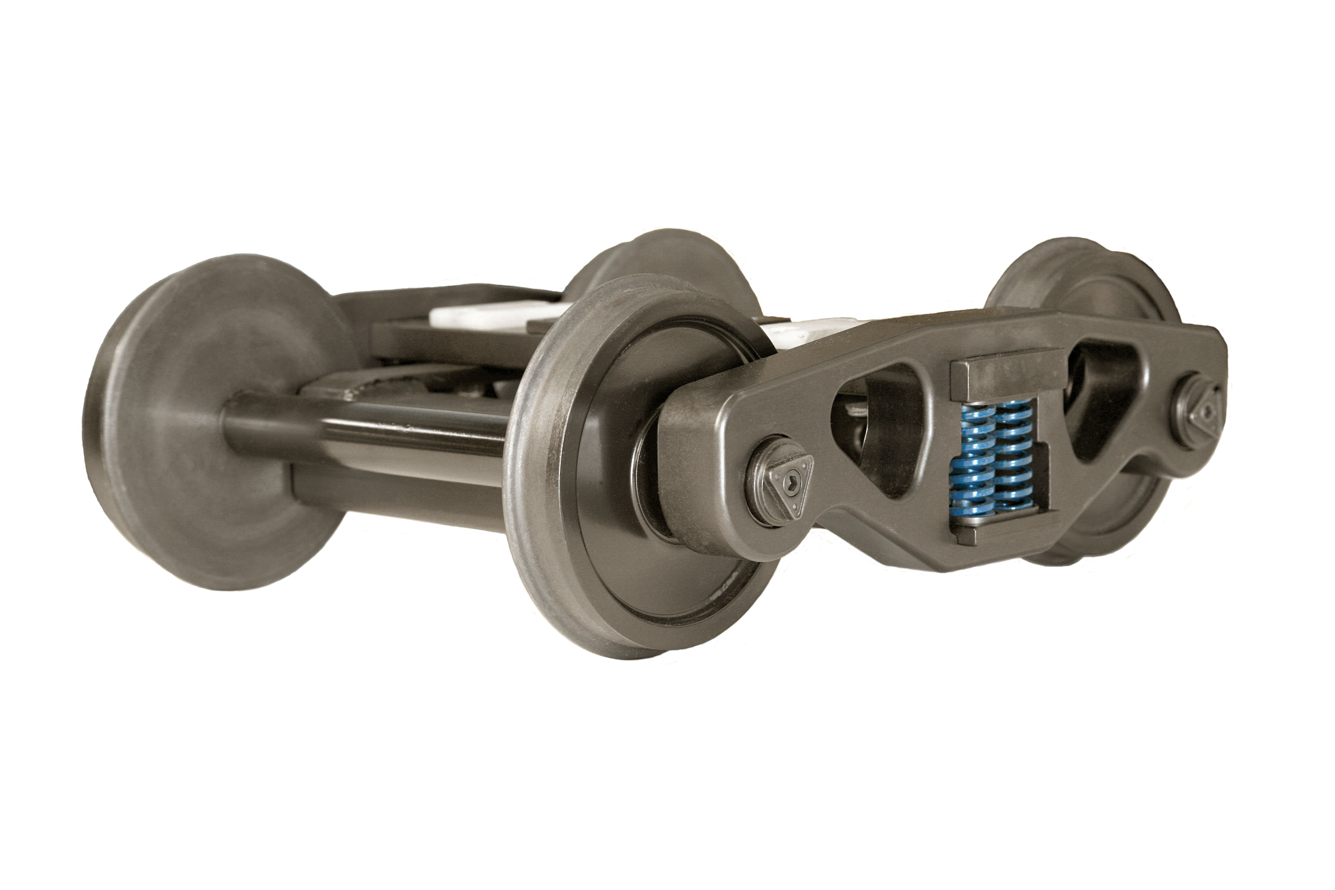
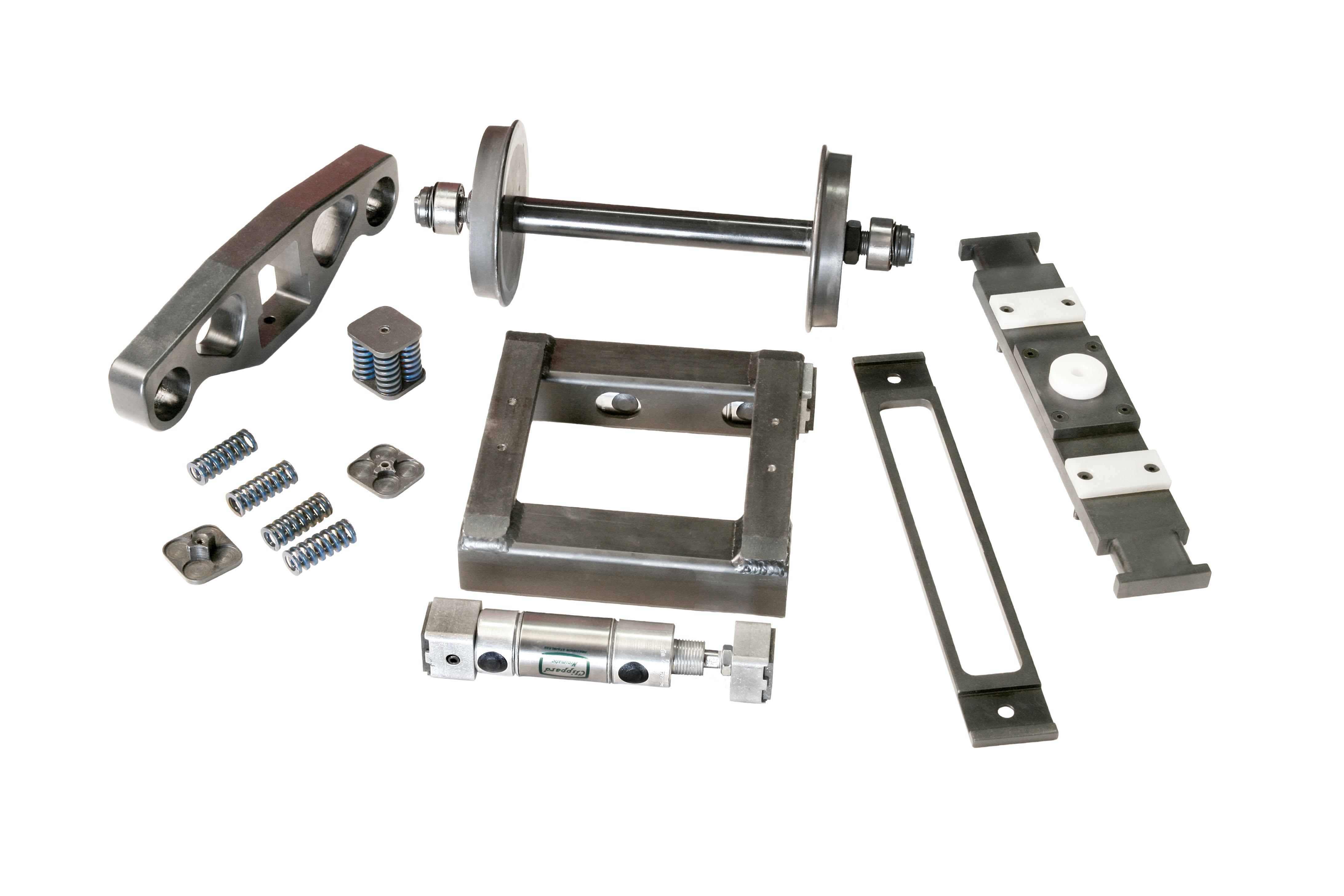
We have come up with a design to overcome the sliding friction problem. Each wheel has it's own bearing and the axle does not rotate. The ends of the axle are spherical and fit into a 7/8" bore truck side frame which seems to be the most common size. This allows the truck to flex as it goes around the track with the inevitable small dips etc. A spreader bar between the bottom of the side frames is necessary to prevent the frame from twisting. This twist occurs with any self-aligning bearing due to the fact that the centerline of the load is not precisely in line with the centerline of the bearing causing the side frame to want to twist. 5202 double row sealed ball bearings are used. These bearings are preloaded and have a rather high contact angle of 25¯ enabling the bearing to take the moment load involved in rounding a curve. A single row bearing is not designed for such service, see reference 1. The typical bearing used is an S3K 3/8" bore and a 7/8" O.D. The 5202 bearing has a bore of 0.5906" and an OD. of 1.3780". The 5202 bearing has a life 47 times greater than the S3K. The two bearings are shown side-by-side in Fig. 1. The parts that make a wheel sub-assembly are shown in Fig. 2. These parts are the wheel, the bearing, bearing retainer, Grade 8 retaining bolts and spiral spring lock washers. The parts that make up one end of the complete assembly are shown in Fig. 3. One end of the axle is shown with the wheel sub-assembly, the combined bearing retainer and support and the grade 8 bolt that holds the assembly together. A photo of the completed assembly is shown in Fig. 4. All of the parts are made of a medium grade steel.
In use it was found that the free-wheeling design resulted in truck instability wherein the two axles could shift into a parallelogram (called warping by the railroads). Derailing then was possible. Observation of the truck behavior at a particular facing switch showed that with the wheel shifted into the parallelogram shape the wheel approaching a closed switch point would climb the rail. This problem was solved by attaching a piece of 0.030" thick sheet steel across both axles with four clamps as shown in Fig. 5. The truck is shown up-side-down in this Figure. This resulted in warp stiffness yet allowed the wheels flexibility to follow an uneven track. The axle clamps and sheet metal were custom made for each style of truck. The holes in the sheet metal for the clamps were marked for each assembly to assure that the truck assembly was "square".
Of course there is no free lunch. There is a tolerance stack-up problem that must be considered. With a conventional configuration the back-to-back dimension is controlled only by the distance between the axle shoulders. In the free-wheeling design the additional tolerances that must be considered are the depth of the bearing bore in the wheel and the bearing width. The net result is a rather close axle shoulder-to-shoulder tolerance. To make this design practical all of the parts were made with precision NC equipment.
Both of us have all our cars, equipped with the new wheels. There are a number of locations around the Los Angeles Live Steamers track with the combination of a grade and a curve. This wheel arrangement has demonstrated a significant reduction of pulling power on curves compared to the fixed wheel-axle configuration. A much better life should result not only because the bearings are larger, but the problems addressed in Ref. 1 have been eliminated.
Some consideration has been given to making this assembly available to others. Experience has shown that that there are considerations that must be taken in the rework of existing truck side frames and the installation of the sheet metal for warp stiffness. Various truck designs have their own axle center distance and distance from the bottom of the bolster and the centerline of the axle. The only way to handle this problem is to provide a complete truck assembly.
Ref. 1 "What's Wrong With Those Bearings" by Wilbur F. Wilhelm, page 16 November 2000 Modeltec.